Want to print small parts with your stock FDM printer ?
Most of the time our customers report troubles with small parts. We’ve made a first guide to help you without going deep into settings. Today it’s time to dive deeper in the slicer ! There are few advices to simply perform precision and small parts with our STLs and more.
Note: we assume that your printer is well set and good condition.
#1 A good slicer
After long time with Cura, we tried Prusaslicer, the difference was here. On big part, not much, but small parts are so clean ! We wont present that slicer, you have lot of videos and articles about it but mostly the best. Without entering into details, the GCODE generated makes more sens for our application.
#2 Match profiles
Whatever your slicer, you’re able to set different types of printing profiles. For exemples, ours:
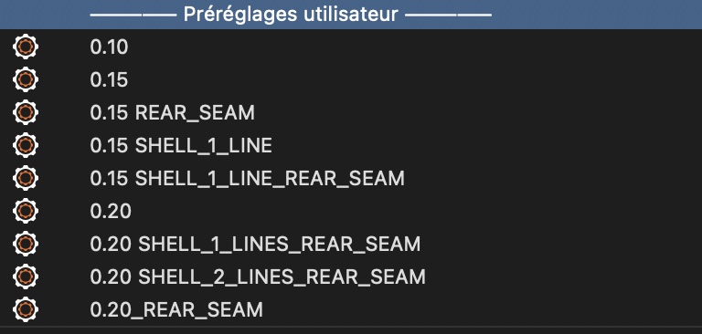
To well set each profile, you firstly need a good one as reference. So, first use the default profiles for your printer if available and same for the material. We use to start on 0.2 mm layer profiles as reference. Once your print is good with that default profile we could start to play.
Our reference is (for 0.4mm nozzle):
Profile name: 0.2
- 1st layer: 0.2 mm
- layers: 0.2 mm
- perimeters: 2
- infill: 5% GRIDE pattern
- supports: no (by default but changed for each print if needed)
- seam: shortest
The rest is pretty simple, once your reference profile is done, in our case 0.2, we could create the others just by changing few values with almost no risk:
Profile name: 0.15 (e.g. landing gears, skids)
- 1st layer: 0.2 mm
- layers: 0.15 mm
- perimeters: 2
- infill: 5% GRIDE pattern
- supports: no (by default but changed for each print if needed)
- seam: shortest
Profile name: 0.15 REAR_SEAM (e.g. helicopter tail)
- 1st layer: 0.2 mm
- layers: 0.15 mm
- perimeters: 2
- infill: 5% GRIDE pattern
- supports: no (by default but changed for each print if needed)
- seam: rear
Profile name: 0.15 SHELL_1_LINE (e.g. rotor blades)
- 1st layer: 0.2 mm
- layers: 0.15 mm
- perimeters: 1
- infill: 0%
- supports: no (by default but changed for each print if needed)
- seam: shortest
Profile name: 0.15 SHELL_1_LINE_REAR_SEAM
- 1st layer: 0.2 mm
- layers: 0.15 mm
- perimeters: 1
- infill: 0%
- supports: no (by default but changed for each print if needed)
- seam: rear
Profile name: 0.2
- 1st layer: 0.2 mm
- layers: 0.2 mm
- perimeters: 2
- infill: 5% GRIDE pattern
- supports: no (by default but changed for each print if needed)
- seam: shortest
Profile name: 0.2 REAR_SEAM (e.g. fuselage, wing)
- 1st layer: 0.2 mm
- layers: 0.2 mm
- perimeters: 2
- infill: 5% GRIDE pattern
- supports: no (by default but changed for each print if needed)
- seam: rear
Profile name: 0.2 SHELL_1_LINE
- 1st layer: 0.2 mm
- layers: 0.2 mm
- perimeters: 1
- infill: 0%
- supports: no (by default but changed for each print if needed)
- seam: shortest
Profile name: 0.2 SHELL_1_LINE_REAR_SEAM (e.g. elevator)
- 1st layer: 0.2 mm
- layers: 0.2 mm
- perimeters: 1
- infill: 0%
- supports: no (by default but changed for each print if needed)
- seam: rear
Profile name: 0.2 SHELL_2_LINES_REAR_SEAM (e.g. prop)
- 1st layer: 0.2 mm
- layers: 0.2 mm
- perimeters: 2
- infill: 0%
- supports: no (by default but changed for each print if needed)
- seam: rear
Now we have all of our profiles almost ready, you need to test them first to check if everything is ok. They have to be exactly the same except those values. Those are printing profiles so that means independent of material profiles. Whatever the material, you should be able to use the same printing profile no matter the material.
#3 Small parts
We have one limitation, the nozzle diameter, so the printing profiles will help you to deal with. Using 0.15 mm, 1 perimeter and no infill will not deform your print with extra material.
For exemple, printing our helicopter’s blades with 5% infill and 2 perimeters will give you a messy result. Using no infill and only 1 perimeter will give you a clean one !


#4 Precision
We design our models with 0.2 mm play to 0.1 mm following the part. As seen previously, if any extra material or small blobs are printed you wont be able to assemble correctly. By removing extra material gives you more accurate details and a better fitting.


#5 The right profile at the right place
Of course, if your part needs specials constraints, you need to adapt the profile. When we produce parts for an aircraft (a real one), we wont use no infill and 1 perimeter… Remember, less material, more problems.
#6 Fine adjustment
To finish, if your profiles work well but need few improvements you could changes few settings to make it perfect. When you print small parts, it’s common to reduce filament flow between 100 and 95%. Travel and print speed could also change.
Using this and the previous article “Tips & tricks” you should be able to reach our printing quality. If not, contact us !
